


Abstract
!A. Three-phase unbalanced AIoT correcting device
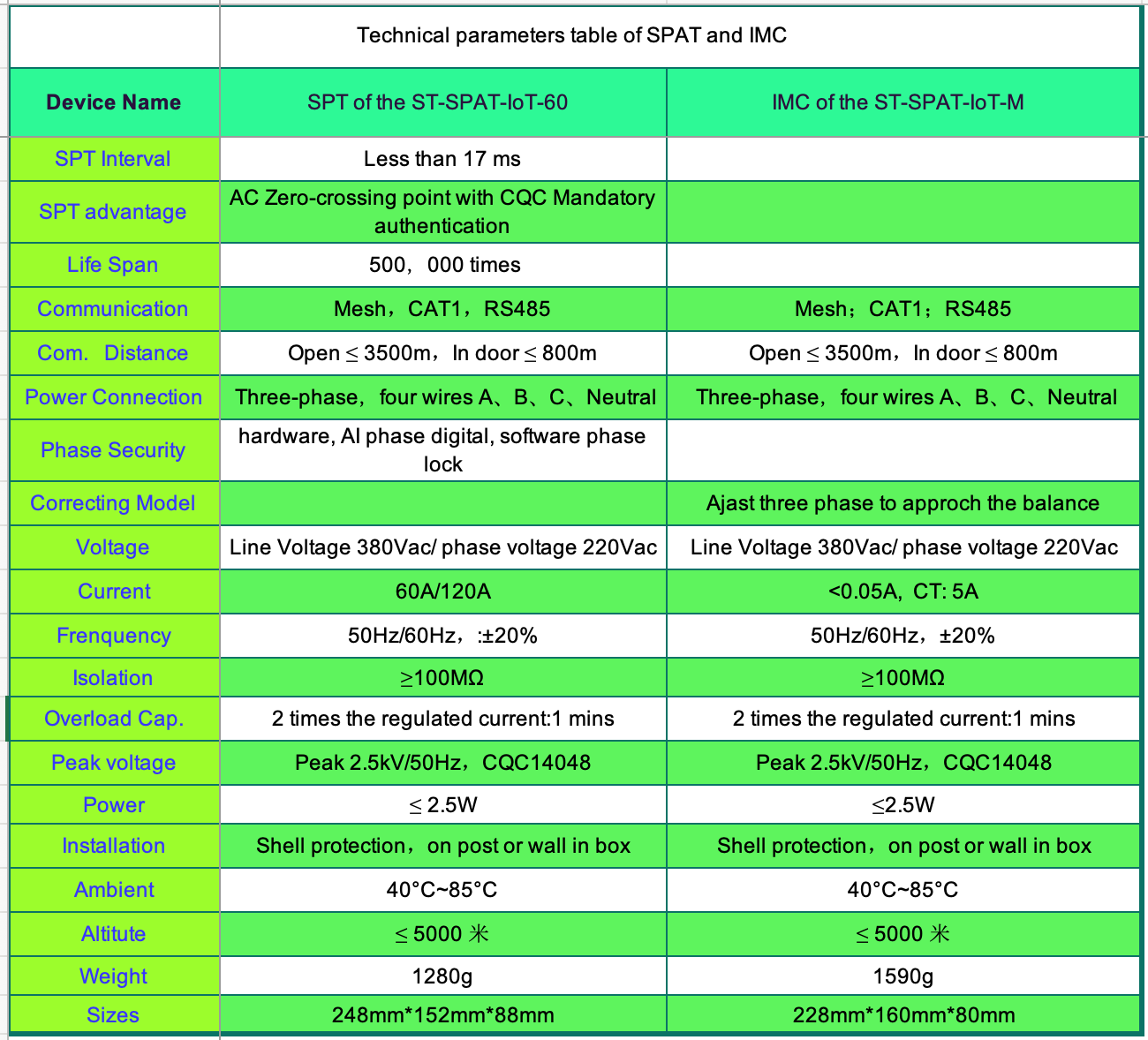
2B Technical parameter
3C. Causes of three-phase imbalance
4D. What are the hazards of the three-phase imbalance?
5D How to deal with the three-phase imbalance?
Abstract
The three-phase electrical imbalance rate is an essential indicator of power quality. There are many factors affecting the power system. The three-phase imbalance is expected because the electrical load characteristics on the power demand side are: thousands of households, ever-changing, and all kinds of states. Therefore, three-phase electrical load types, power distribution line parameters or three-phase load asymmetry lead to three-phase imbalance. Typically, the three-phase voltage and current are usually unbalanced. If the three-phase imbalance exceeds the range that the distribution network can withstand, the safety of the power application will be affected. If the current on the neutral line exceeds a specific value, it might cause a power safety accident. At the same time, the power loads like motors will be unsmooth and dangerous when the three-phase asym exceeds the limit when the motor’s run is harmful, causing problems such as more considerable energy consumption, significant vibration and power output decline.
1A Three-phase unbalanced AIoT correcting device
System composition
Suntrans Measurement & Control System Co., Ltd.(Abbr., Suntrans Control™) has been engaged in the "Power Internet of Things & Electrical Power Intelligence" for 30 years, especially the innovation of the electrical AC zero-crossing-point (Arc-free) relay protection controller, leading the power distribution system from the era of arc extinction to electricity arc-free. In the arc-free era, the service life of the power controller has reached the million switch times level, significantly improving the reliability and safety of the power distribution management & control system.
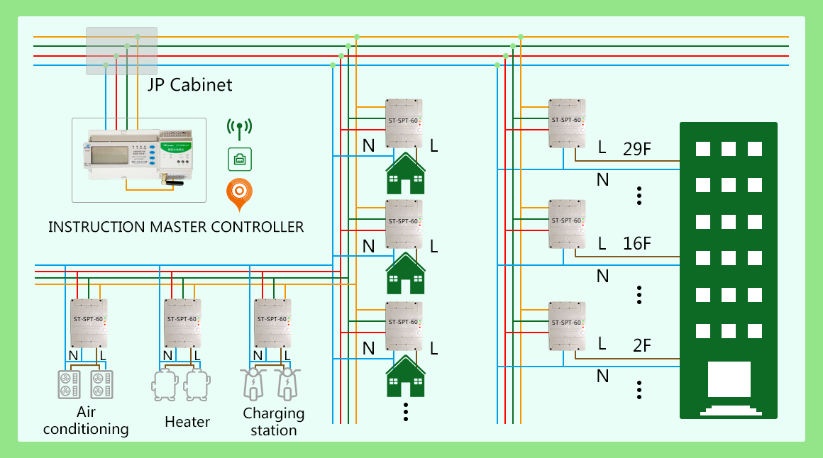
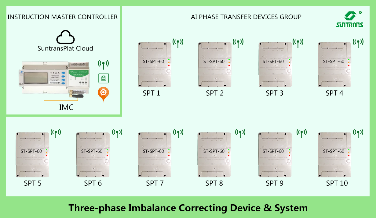
The relay protection controller embedded with AC arc-free technology is used to realise the intelligent phase transfer to balance the three-phase from imbalance. (abbr. as Smart Phase Transfer or SPT in abbreviation) based on the contactor. The system consists of an "Instruction Master Controller" (IMC in abbreviation) and "AI Phase Transfer" on the power side, echoing the "SuntransPlat Cloud Platform" (SCP in abbreviation). The three parts are a phase imbalance management system. The IMC is responsible for collecting the real-time electrical operation data of the power transformer station, dynamically analysing the three-phase voltage, three-phase current and the power neutral-line current of the transformer station branch output and the installation location of the IMC, and synchronously analysing the three-phase load voltage and current of a large number of "AI commutators" installed at the lower stage. According to the topology distribution of three-phase voltage and current, the asymmetric governance analysis decision is made, and instructions are sent to the "SPT"; when the "SPT" receives the instruction from the IMC, the phase transfer instruction is accurately executed; the IMC and the SPT have reliable communication within the range of 3.5 km, with the ability to synchronously send the relevant parameters of the distribution system to the IMC and the SCP in real-time. According to the power station's transformer capacity and dynamic regional imbalance, this system intelligently realises the three-phase dynamic balance and monitors the neutral-line current. Each station can have an IMC and several SPT devices.
System features
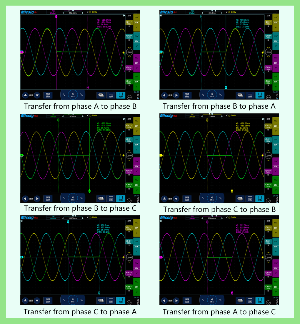
The phase transition interval technology of the AC arc-free 17-millisecond transfer by the contactors gets 100% electrical safety isolation and phase transition, with UPS-level uninterrupted and inductive switching characteristics. The phase transfer time is less than 17 milliseconds, the phase transfer is accurate at the zero-crossing point of the electrical AC power, and the process is accurate and controllable. The phase transfer process is completed by an intelligent AC zero-crossing point power contactor that has passed the mandatory certification of power CQC14048, and there is no arc in the phase transfer process. Due to AC arc-free technology, there is no surge flow in the phase transfer process, and the phase transfer is stable and reliable. Because the commutation time is switched at the zero-crossing point of the voltage, there is no voltage mutation and no inrush current. Accurately locate the SPT to ensure the balance of each branch of the distribution network. The unique segment-by-stage voltage drop comprehensive algorithm prioritises the nearest phase transfer to the extreme value of the line imbalance to ensure the optimal balance of each part of the line, more effectively reduce the neutral line current, and improve the terminal power supply voltage. There is no adverse effect on all kinds of electrical equipment. Isovoltage voltage AC zero-crossing point senseless phase transfer technology will not cause power supply interruption and temporary voltage drop. Even the most sensitive digital equipment is insensitive, which does not affect the user's electricity consumption, and can be stable and reliably transferred for inductive, capacitive and resistive loads.
Flexible functions
The AI commutator is entirely digitally designed. Its phase transfer parameters can be factory set and adjusted by those strictly identified through the cloud. According to the AI system machine learning, AI reset can be implemented. Users can limit the App configuration of the SPT according to their needs, including but not limited to load rate, imbalance, neutral line current, etc. Only when the set conditions are met can the SPT intelligently adjust the phase transfer to meet the three-phase to relative balance; SPT is a relay protection device, so all its parameters can be configured, including load protection, temperature protection, triadic protection, etc. The overload warning value of the load current controlled by the phase transfer switch will be issued through the applet or WhatsUp. When the protection overload is exceeded, the SPT will cut off the load and enter the closed protection state of the SPT to prevent short circuits or overload damage to the user's device and the SPT on the load side. The overload protection parameters can be adjusted in the setting. The IMC has a variety of communication methods, which is convenient for management and control; Mesh wireless communication networking is used between the IMC and SPC.
Each IMC is embedded with CAT1, Mesh, and RS485 communication interfaces; Each SPC is embedded with composite communication interfaces such as Mesh, RS485 or wifi, referring to the IMC has the function of sharing data with other digital electrical equipment or electrical control systems. The Could platform implements layered control and can implement large-scale deployment. District area control can be controlled according to the place of origin, district area code, SPC, and top-down system control. In large-scale deployment, the topology of the distribution network is straightforward. The product's life cycle is controlled, the health status is diagnosed in real time, and the system is safe and reliable. Each SPC ensures that the number of phase transfers is at least 500,000 times. The SPC will enter the warning state when the number of phase transfers is close to 500,000. The relevant numbered products issued by the App will enter the operation and maintenance period, informing the user that the spare parts must be replaced.
Technical parameter
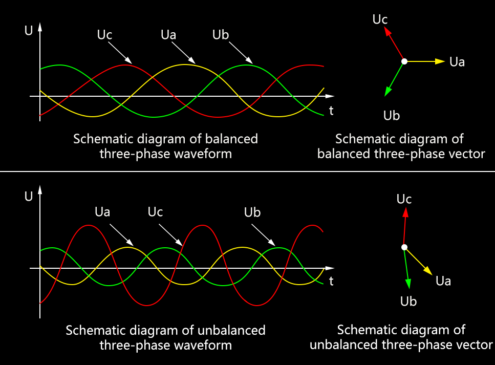
Three-phase imbalance means that the amplitude of the three-phase current (or voltage) is inconsistent in the power system, and the amplitude difference exceeds the scope of electrical safety regulations. The occurrence of a three-phase imbalance is related to the user's power load characteristics and the power distribution planning and load distribution of the distribution system. Three-phase equilibrium mainly refers to the equal size of the three-phase voltage. If it is arranged in the order of A, B and C, the angle between them is 2n/3. Three-phase imbalance refers to the inconsistency of phase size and angle. The allowable imbalance of three-phase voltage of power quality (GB/T15543-1995) is suitable for an AC-rated frequency of 50 Hz or 60 Hz. Under the normal operation mode of the power system, the voltage imbalance of the PCC point connection point is caused by the harmful sequence component. The standard stipulates that the allowable value of imbalance under the normal operation mode of the public connection point of the power system is 2%.
The three-phase current imbalance calculation method generally has the following two commonly used formulas:
Imbalance % = (maximum current - minimum current) / maximum current × 100%
imbalance % = (MAX phase current - three-phase average current) / three-phase average current × 100%.
For example, the three-phase current is IA =9A IB=8A IC=4A, then the three-phase average current is 7A, the phase current-three-phase average current is 2A 1A 3A respectively, and the difference is the largest, so MAX (phase current-three-phase average current) = 3A, so the three-phase current imbalance = 3/7.
Causes of three-phase imbalance
The reasons for three-phase voltage imbalance are: three-phase load distribution is uneven, single-phase grounding, disconnection resonance, etc.
Reason for three-phase load is uneven
Due to many reasons, electrical designers, especially installers, must pay attention to the three-phase load balance. When the electrical load is connected to the distribution box, the three-phase load balance is not effectively controlled, which is the starting cause of the imbalance of the three-phase load. Secondly, most power distribution systems mix single-phase and three-phase. In single-phase distribution, there is no focus on the three-phase symmetry, which leads to asymmetry and safety hazards and reduces power consumption efficiency, exacerbating the imbalance of the three-phase load of the distribution transformer.
Broken fault
Suppose one phase is disconnected but not grounded, or the circuit breaker and isolation switch are not connected in one phase. In that case, the fuse of the voltage transformer causes three-phase parameter asymmetry. When the first phase of the line of the previous voltage level is disconnected, the voltage of the following voltage level is reduced in all three phases, one of which is lower, and the other two is higher, but the voltage values of the two are close. When the line is disconnected, the disconnected phase voltage is zero, and the unbroken phase voltage is still the phase voltage.
Ground fault
When the line is disconnected in one phase and grounded in a single phase, although the three-phase voltage is unbalanced, the voltage value does not change after grounding. Single-phase grounding is divided into two types: metallic grounding and non-metallic grounding. In metal grounding, the fault phase voltage is zero or close to zero, the non-fault phase voltage increases by 1.732 times and remains unchanged; for non-metallic grounding, the ground phase voltage is not zero but reduced to a specific value, and the other two phases rise less than 1.732 times.
Reasons for resonance
With the continuous investment of various industrial loads, nonlinear power loads have increased significantly. Some loads (such as various frequency converters) generate many harmonics and cause power supply voltage resonance, fluctuation and flashing, and cause three-phase voltage imbalance. Among them: there are two kinds of three-phase voltage imbalance caused by resonance (non-linear loads such as frequency converters):
Base frequency resonance
The characteristics are similar to single-phase grounding; that is, the voltage of one phase is reduced, and the voltage of the other two phases increases. Finding the fault point when Special users can be checked takes work. If it is not the grounding reason, it may be caused by resonance.
Frequency-sharing resonance
The other is frequency-sharing or high-frequency resonance, characterised by a simultaneous increase in three-phase voltage.
The continuous change in electricity load
The fundamental reasons for the instability of electricity load include demolition, the increase of meter transfer or electricity users, the instability of temporary and seasonal electricity consumption, and different living habits in homes and apartments. In this way, the uncertainty and lack of concentration in total quantity and time make the load of electricity change according to the actual situation.
For the monitoring and management of distribution load.
In managing the distribution network, we should emphasise managing three-phase load symmetry. The distribution transformer's three-phase load symmetry is dynamically detected and adjusted in the distribution network's monitoring and control.
4D What are the hazards of the three-phase imbalance?
Increase the power loss of the line
In a three-phase four-wire power supply network, when the current passes through the line, power loss will inevitably occur due to the impedance, and the loss is proportional to the square of the passing current. When a three-phase four-wire system powers the grid, the three-phase load imbalance is inevitable due to a single-phase load. When the three-phase load runs unbalanced, the neutral line has a current passing through. In this way, not only the phase line has a loss, but also the neutral line has a loss, thus increasing the loss of the grid line.
Increase the power loss of the distribution transformer.
The distribution transformer is the leading power supply equipment of the power distribution grid. When it operates under a three-phase load imbalance, it will cause an increase in the distribution loss because the configuration's power loss varies with the load's imbalance.
Distribution output reduction
When the distribution is designed, the helical structure is designed according to the load-balancing operating conditions. The winding performance is the same, and the rated capacity of each phase is equal. The rated capacity of each phase limits the maximum allowable output of the configuration. If the configuration runs under a three-phase load imbalance, the phase with a light load has the surplus capacity, thus reducing the configuration output. The reduction of its output is related to the imbalance of the three-phase load. The greater the three-phase load imbalance, the more significant the reduction of the distribution output. For this reason, when the configuration runs when the three-phase load is unbalanced, its output capacity cannot reach the rated value, its standby capacity is reduced accordingly, and the overload capacity is also reduced. If the configuration runs under overload conditions, it is straightforward to cause the configuration to heat, and in severe cases, it may even cause the configuration to burn.
The spending generates a zero-sequence current
A zero-sequence current will be generated when the spending runs under a three-phase load imbalance. The current will change with the degree of three-phase load imbalance. The greater the imbalance, the greater the zero-sequence current. If the operation has a zero-sequence current, a zero-sequence magnetic flux will be generated in the core. (There is no zero-sequence current on the high-voltage side) This forces the zero-sequence magnetic flux to pass through only with the fuel tank wall and the steel member as a channel, while the magnetic permeability of the steel member is low. When the zero-sequence current passes through the steel member, magnetic hysteresis and eddy current, The modified winding insulation accelerates the ageing due to overheating, decreasing the equipment's service life. At the same time, the memory of zero-sequence current will also increase the loss of configuration.
Affecting the safe operation of electrical equipment
The distribution is designed according to the operating conditions of three-phase load balancing, and the resistance, leakage resistance and excitation resistance of each phase winding are the same. When the configuration runs when the three-phase load is balanced, the three-phase current is equal, and the voltage drop of each phase in the configuration is the same. The three-phase voltage of the configuration output is also balanced. Suppose the configuration runs when the three-phase load is unbalanced. In that case, the output current of each phase is not equal, and the internal three-phase voltage drop of the configuration is not equal, which will inevitably lead to the three-phase imbalance of the configuration output voltage.
At the same time, the configuration runs when the three-phase load is unbalanced. The three-phase output current is different, and the neutral line will have a current passing through. Therefore, the neutral line produces an impedance voltage drop, resulting in neutral point drift and changes in the voltage of each phase. The one-phase voltage with heavy load decreases, while the one-phase voltage with light load increases. Power supply under voltage imbalance, that is, it is easy to cause the user's electrical equipment with a high voltage to burn out. In contrast, the user's electrical equipment with a low voltage may not be available. Therefore, when the three-phase load is unbalanced, it will seriously endanger the safe operation of the electrical equipment.
The efficiency of the motor is reduced
The configuration runs under the three-phase load imbalance, which will cause the three-phase imbalance of the output voltage. Because there are three voltage elements of positive sequence, negative sequence and zero sequence in the unbalanced voltage, when this unbalanced voltage is input into the motor, the negative sequence voltage generates a rotating magnetic field opposite to the rotating magnetic field generated by the positive sequence voltage, which plays a braking role. However, the motor still rotates toward the positive magnetic field because the positive magnetic field is much stronger than the negative magnetic field. Due to the braking effect of the negative sequence magnetic field, the output power of the motor will be reduced, resulting in the reduction of the efficiency of the motor. At the same time, the temperature rise and reactive power loss of the motor will also increase with the imbalance of the three-phase voltage. Therefore, it is uneconomical and unsafe for the motor to operate under a three-phase voltage imbalance.
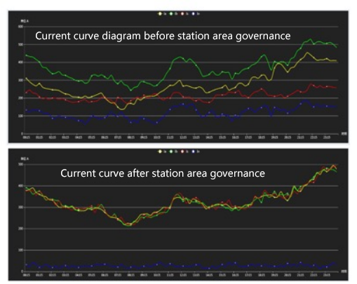
The simplest way to solve the three-phase power imbalance is to adjust the load, transfer the load from the unbalanced phase to the equilibrium phase, and reduce the load difference between them. Through the construction of three-phase asymmetric power monitoring and load AIoT three-phase imbalance management system, through AI dynamic analysis of the power load and three-phase mismatch. The degree of weighing is to implement SPT, IMC and the SCT cloud adjustment of the installed "three-phase unbalanced AIoT treatment device & system" to achieve a three-phase dynamic balance and meet the safety operation index of electricity.
- 在线实时演示
- Suntrans Plat 能源“云平台”演示
- 产品文件中心
- PWA安装说明